Product category
Programmable
Generation
First generation
Supported products
2D and 3D LiDAR sensorsImage-based code readersBar code scannersRFID read/write deviceDisplacement measurement sensorsIncremental and absolute encodersPhotoelectric sensors
Processor
4 Core PowerPC CPU
Flash memory
512 MB in total, 427 MB of which available for applications
Programming software
SICK AppStudioCan be programmed within the SICK AppSpace environment
Toolkit
SICK algorithm API
Further functions
FPGA for I/O handlingDedicated fieldbus controller
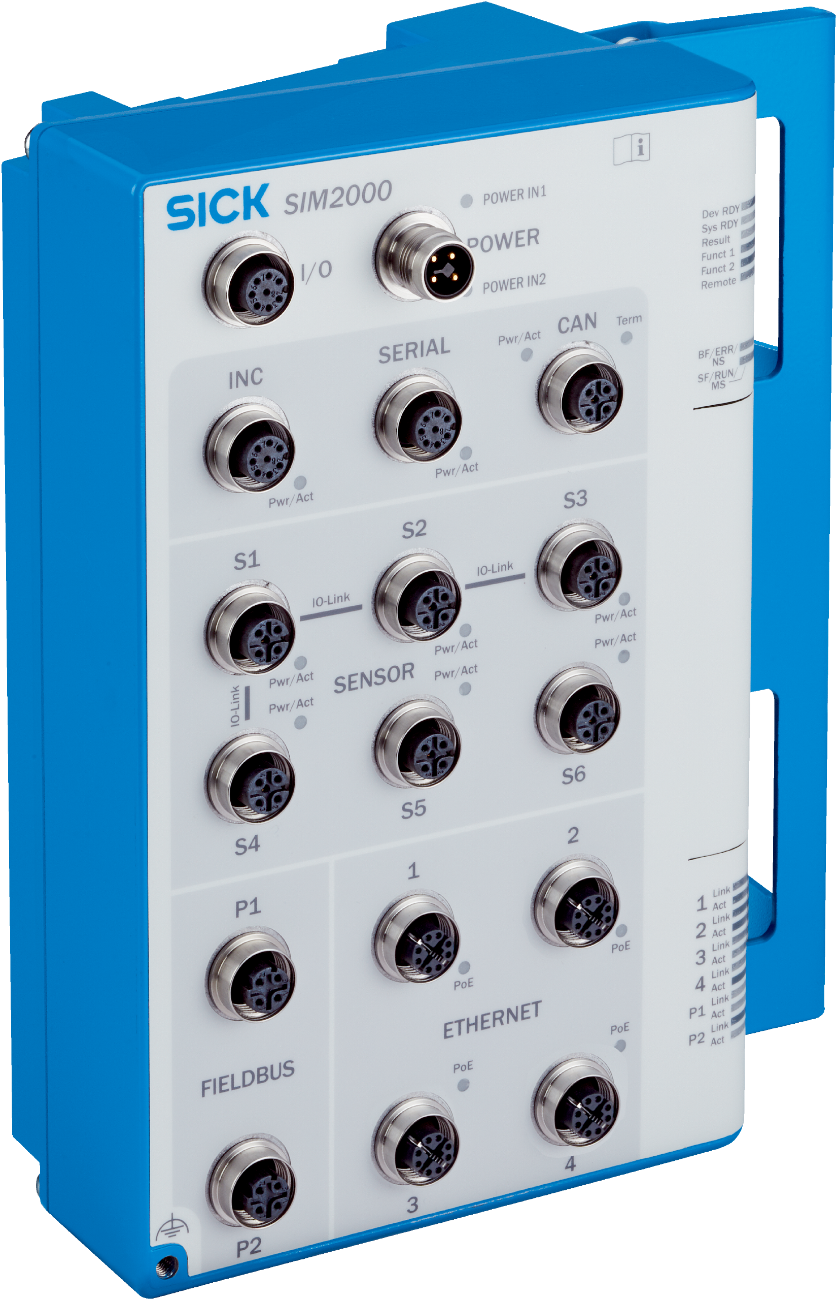
Power, IO-Link Master, output, Input A, Input B, Serial A, serial B, CAN, Ethernet, Fieldbus, USB
X1, X2, X3, X4, X5, X6, X7, X8, X9-X12, X13-X14, 1 x Micro-B, spring terminal, spring terminal, spring terminal, spring terminal, spring terminal, spring terminal, spring terminal, spring terminal, RJ45, RJ45
Supply voltage
24 V DC, ± 10 %
Power consumption
Typ. 20 W, without connected sensor
Power output
≤ 50 W, Input A & B, IO-Link
X1 switching output
100 mA (per output)
X3 switching output
700 mA (total)
X1 voltage supply
≤ 700 mA (total)
X4, X5 voltage supply
700 mA
Housing material
Aluminum die cast
Housing color
Light blue (RAL 5012)
Dimensions (L x W x H)
137 mm x 196 mm x 81 mm
Ethernet
✔ (4) , TCP/IP, FTP, OPC UA, MQTT
Type of fieldbus integration
GigE machine vision/GenICAM
PROFINET
✔ (2) , RS-232, RS-422, RS-485
EtherNet/IP™
✔ (2) , USB 2.0
Data transmission rate
RS-232: 115,2 kBaud, RS-422/RS-485: 2 MBaud
Function
For configuration
Operator interfaces
Web server (GUI), SICK AppStudio (programming), SICK AppManager (app installation, firmware update)
Data storage and retrieval
Image and data logging via optional microSD memory card, internal RAM and external FTP
Memory card(s)
Industry-grade microSD memory card (flash card), max. 32 GB, optional
IO-Link Master
4 inputs, 4 inputs/outputs (configurable incl. IO-Link)
Output
4 outputs (insulated)
Input A/B
4 inputs each (insulated)
Control elements
1 selector switch (under the servicing panel)1 functional button (under the servicing panel)2 S1 and S2 switches for GND ISO/GND
Electromagnetic compatibility (EMC)
EN 61000-6-2:2005-08EN 61000-6-4:2007+A1:2011EN 61131-9:2013-12
Shock load
EN 60068-2-27:2009-05
Ambient operating temperature
0 °C ... +50 °C1)2)
Ambient temperature, storage
–20 °C ... +70 °C1)
EU declaration of conformity
✔
UK declaration of conformity
✔
ACMA declaration of conformity
✔